x•s•v•toys (ex-es-iv-toyz or excessive toys): Exceeding a normal, usual, reasonable, or proper limit for the purchase of consumer electronics. |
|
x•s•v•toys (ex-es-iv-toyz or excessive toys): Exceeding a normal, usual, reasonable, or proper limit for the purchase of consumer electronics. |
|
***UPDATE*** This retrofit structured wiring installation has been working with no problems since it was designed and installed in 2006, and most of the concepts are still valid today. However due to advances in technology some of the plans should be changed to accommodate the latest technological developments. Please review THIS UPDATE (CLICK HERE) before proceeding with any new plans for a home structured wiring project.
You will need to get some wiring to get this job done of course. For this plan, we need two types of wire: Cat5e and RG6 coax. But, how do you know how much you need to buy? Buy too much and you waste money, buy too little and you might come up short in the middle of work which will be a great pain. Luckily, if you buy in bulk bundles they are not expensive at all. The amount of money you spend on actual wiring will be small in relation to the whole budget.
You can make an approximation of the wire needed and add a fudge factor and you should come out OK. Take a tape measure and make a rough estimate of the distance from the SMC to each wall plate. Then make a chart showing each wall plate and the length of each wire going to it. You need to add extra to account for routing such as down the walls from the attic. Be plenty generous with your estimates because wire is cheap and you don't want to be short. Below is a sample of how you might do this using a spreadsheet. The left 3 columns list the destination of each wire, the type of wire, and the estimated length. The right 3 columns contain the same data sorted by wire type so that the total length of each type can be easily calulated. It shows just under 900 feet each for the Cat5e and the RG6, which is convenient because they are very economical in packs of 1,000 feet. (WP = Wall Plate and DP = Demarcation Point).
So for this project, one 1,000 foot roll of Cat5e and one 1,000 foot roll of RG6 did the trick. Sometimes installers will prefer to use two 500-foot rolls instead of a single 1,000 foot roll because it allows them to pull a 2-wire run from the two rolls at once, which is more convenient than pulling out a long run and then doubling it from a single box. Either way will work.
We have drawn out where we want all the wiring to go. Now it is time to actually put the wiring in. This is "structured wiring" after all. Unfortunately, I cannot tell you exactly how to do this. Even if I tried, odds are it would do you no good because each situation is different. There is not much in the way of "high-tech" here, it is just a matter of getting the wire into place by starting at one end and working to the other. In this case the wiring is all laid in the attic, and gets to each wall plate by coming down the wall. This requires that a hole be drilled up in the attic on top of the wall, then the wires are dropped down that hole. A hole also needs to be cut into the wall where you want the wires to come out to the wall plate. This process requires knowledge, patience, and a number of specialized tools such as super-long drill bits, fish rods, and so forth. While it definitely is possible for a semi-skilled do-it-yourselfer (preferably with a partner) In my case, I paid some experts to do the job :). If you go this route, it is very important that you have everything precisely defined so they know exactly what cables need to go to each location.
As the wire is being installed, it is a good time to label it as well. With more than 40 wires coming into the SMC and multiple wires at each wall plate, if there is not some sort of labeling scheme it is going to be difficult to figure what wire is going where later. It is possible to use various methods to identify wires one they have already been installed, such as with tone generator tools, but I vote for the easier way of doing it as they are being put into place.
There are different ways that you can label your wire, including using specialized label makers made just for this purpose. You can even simply write on the wire jacket with a permanent marker. I decided to use my own color-coded labeling scheme using commonly found (and inexpensive) tie wraps as the labels.
Wire Ties (or Tie Wraps)
Using the wire ties gives a few advantages beyond being simple and cheap. They are very durable once put into place and unlikely to ever fade or fall off over the years, and they can easily be removed and replaced allowing for flexibility for reconfiguring if necessary. The key to this system (and for any system) is to define a logical labeling system, make sure it is strictly followed, and then write everything down because you are sure to forget something if you try to keep it in your head!

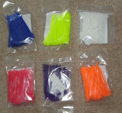
The color coding system uses a 2-part system. The outmost tie identifies the wall plate location and the innermost tie identifies the position of that wire in the wall plate. Having determined that the maximum number of ports per wall plate will be 6, we therefore need 6 colors to identify the wall plate port locations. These 6 colors are listed in the above key diagram. The 6 colors are listed in alphabetical order although this isn't really necessary, it just seems tidy : ) This system depends on always following the same numbering scheme for wall plate ports where #1 is at the upper left, 2 is the next one to the right, and so forth as shown in the picture. If the plate only has 4 ports, then there will be ports 1-4 instead of 1-6 and the color coding will remain consistent. The wall plate numbers are assigned to the different wall plates in no particular order, the important thing is to make sure they are all different and to record what they are. A good way to do this is to color-code the wall plate symbols on the floor plan:
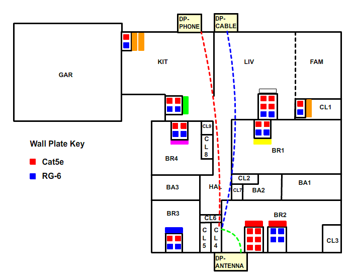
Due to running out of different colors of tie wraps for identifying the wall plates, the kitchen wall plate wires are indicated by a double-orange (2 orange tie wraps) to differentiate them from the wires in Closet 1. Also, note that the wall plates in Bedroom 2 have been reconfigured into one 6-port plate for 6 Cat5e cables and one 4-port plate for 4 coax cables. Both can be labeled with red since it will not be ambiguous which wall plate is which (they each have different types of wires).
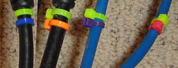
As the wires are put into place, each end is labeled according to the color-coding scheme. This will allow for a clear understanding of where every wire goes from the SMC which will be important later for connecting everything together. A typical bundle of 4 wires at the wall plate location is shown here. The wires are labeled in the same way at the other end in the SMC. Following the color coding scheme, these wires belong to the wall plate in BR1 (yellow outer tie wrap). When the wires are installed in the wall plate ports, they will be in ports 1, 2, 3, and 4 from left to right, following the wall plate color coding scheme: 1-blue, 2-orange, 3-purple, 4-red.
Don't forget that the infeed lines (dotted lines in the above floor plan) also need to be put into place. If you want to keep your existing phones and cable functioning while you work on the rest of the SW project, then lay these wires into place and place the far ends next to to the DP (Demarcation Points) with some extra wire to allow for installation (at least 5 feet extra). This way, you can install the entire SW system while keeping the old system running, and when you are ready to "make the switch", it will be a quick job at the DP. This will be covered later.
There is no particular reason you have to install all of the wall plates first, it just the way I decided to do it. Based on our previously-made floor plan we know what wires we want at each wall plate, and hopefully at this point all of the wires have been physically put into place to match the plan. Those wires will be coming out of a hole in the wall and the wires will be simply cut off at the ends, so now it is time to put connectors on them and make them into tidy-looking wall plates. To do this, some more decisions need to be made because there are different ways to do things. There is no right or wrong way as long as it works, so you have to pick the way that suits you.
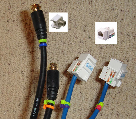
First you need to decide on how you want your wall plates to be configured and how you want them to look. Two basic options are to get preconfigured and fixed all plates, such as the one shown below on the left which has 2 Cat5e and 2 coax jacks, or to go with a modular system that uses snap-in connectors (also called keystones) that you pick and choose for each plate as shown on the right. Both of these come in different variations such as Decora style and also can be had in different colors.

My decision was for the modular option on the right. Once again, because I like the idea of flexibility and this system allows the possibility for reconfiguring the ports in a wall plate if that should become necessary later.
Exactly how the wires will be terminated will be decided based on the wall plate decision. In our case, the termination is determined by the modular port system. For the Cat5e cables, the wire is directly "punched down" onto a "Cat5e keystone insert" which then snaps into one of the wall plate square holes. For RG6 coax, the keystone is a dual-sided F-Type connector that accepts a coax plug on either side, so the RG6 cables are terminated with a standard F-type plug connector. In some cases, as shown below, premade lengths of coax with already-made connectors were used for the wiring job, which simplifies things.
Prior to terminating all the wires, you will need to purchase all of the keystones necessary to do the job. The keystones can get fairly expensive, but they can be purchased for good prices if you shop around. Two of my favorite places are deepsurplus and monoprice. They have excellent prices I have never had a quality issue with any of the parts purchased from these stores.
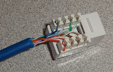
The Cat5e cables need to be properly connected to the keystone jacks in order for computer networking to work. Instructions are provided with the jacks and there are many good tutorials that describe how to do this. The picture below shows a close-up of a Cat5e wire terminated into the Cat5e jack. There are 8 different wires and they all must go into the right spot in the jack. The jack is color-coded to help with this process (you can't see it in this picture).
ANOTHER DECISION - A or B? Before you start punching in all of these Cat5e cables, you have to make a decision between 2 different network wiring standards. These are called T568A and T568B. The order of the wires is different for these two standards. You can obsess about which one to select, but in the end it doesn't matter, as long as you pick one, remember what it is, and follow it throughout your entire project. If you mix and match A and B, you will have problems! Its nothing to worry about, just pick A or B and then follow it (or tell you installer to follow it). There is plenty of information available on the internet about T568A and T568B if you want to learn more. This project is wired as T568A if you are interested.
The final step in this phase is to finish up the wall plates by snapping in all of the keystone connectors into the proper ports (being sure to follow the color-coding scheme!) and screwing the wall plates to the wall. To keep things simple I used 6-port wall plates throughout, even if a specific location was only using 4 ports. Snap-in blanks for the unused ports are easily available and they are cheap. You can use a 4-port plate when there are 4 ports being used it if appeals to you better. Below is an example of a typical finished 4-port wall plate with 2 coax jacks and 2 "RJ45" jacks, which really are more properly called "CAt5e" jacks like you see them labeled.
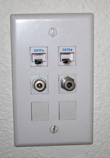
Typical wall plate - Cat5e (RJ45) and 2 Coax (F-type)
