 |
|
x•s•v•toys (ex-es-iv-toyz or excessive toys): Exceeding a normal, usual, reasonable, or proper limit for the purchase of consumer electronics. |
|
 |
|
x•s•v•toys (ex-es-iv-toyz or excessive toys): Exceeding a normal, usual, reasonable, or proper limit for the purchase of consumer electronics. |
|
***UPDATE*** This retrofit structured wiring installation has been working with no problems since it was designed and installed in 2006, and most of the concepts are still valid today. However due to advances in technology some of the plans should be changed to accommodate the latest technological developments. Please review THIS UPDATE (CLICK HERE) before proceeding with any new plans for a home structured wiring project.
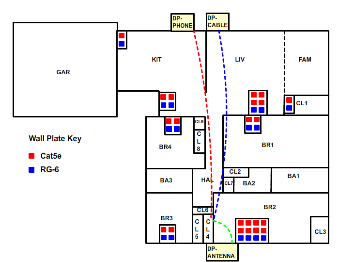
With our demarcation points (DPs) identified and the wiring closet location established it is easy to plan the infeed wiring: This will be a straight run from the DPs to the wiring closet. The infeed lines are dashed to indicate that they are wiring coming IN. This is not due to any standard, its just the way I decided to do it :)

Next is to decide where the wiring will run from the wiring closet out to the different rooms (to wall plates). Just to reinforce what was said earlier, if you are in a new construction job and the walls are open (not drywalled), you have an entirely different situation than with a retro job. In that case, you probably will take an entirely different approach too, which basically will involve running lots of wire all over the place. That's what I would do anyway. The actual wiring itself can be purchased pretty cheap, and the labor to run it all over the place will be much easier due to the open construction. For the retro job, each end point probably will involve a fair amount of pain to get put into place. This is because the wiring needs to routed to the desired wall plate in, around and through whatever has been built into place. Each wiring run that is sent from the wiring closet to a wall plate will probably involve at least a few hours of work.
For this project, the wiring runs up out of the wiring closet into the attic. Laying wire across the attic is a fairly simple job, if a bit cramped, hot and dirty. The final stretch is through the header on top of the wall, down the wall and then through a cutout hole in the bottom. Getting these wires down the wall can be a tedious process and requires special tools such as long flexible drill bits, fishing wires and so forth. Obstacles within the spaces between wall studs such as horizontal “fire block” boards are invisible until you hit them, at which point extra holes may need to be cut in the interior wall (and patched later). Because of all of this work required for each wall plate, the number of end points may be limited for a retro job, unless the budget is unlimited.
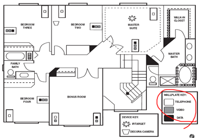
Here is where some of the variability for a SW system comes into play. A typical planning scenario involves deciding on which rooms should have “phone” or “internet” or “television”. For example, in the Leviton Installation Manual for Residential Structured Wiring (V3) a typical recommended arrangement is to organize things in this fashion. Note the wall plates with connectors designated for telephone, video, and data.

This is a reasonable approach, but I elected to view things differently. When the different types of wiring are discussed, multiple terms are often used to describe the same wire. Is it a video cable or is it an RG-6 cable? Is it network cable or Cat5e cable? To me, terms such as “video” or “network” or “data” describe the signal that is coming down a cable. Terms such as “Cat5e” and “RG-6” more properly describe the type of cable itself. Things get confusing due to the fact that a certain kind of cable can carry any one of a number of different things. For example:
So my preference is to think of the cables for what they could do rather than what they will do, and plan such that I can not only accomplish what I need right now, but will have the ability to reassign cables for different tasks down the line. The ability to do this is one of the main purposes of a home run wiring closet anyway. For this job, we will use the 2 different types of cable discussed above: Cat5e network cable, or Cat5e for short, and RG-6 coax cable, or coax for short. These are the 2 most common types of cable recommended for SW jobs as you will see from other SW web sites. Sometimes "phone" wiring or Cat3 is also recommended for phone lines. However, it isn't really necessary because Cat5e will work with telephone with no problems at all. It is basically the same wire but packaged in such a way that it will work for networking. The signal demands for networking are much more stringent that for phone. It is true that the Cat3 cable is a little less expensive than the Cat5e, but really the difference is not that much. Plus, this will create a more flexible system since you will be able to make your own decision at any time as to whether a given jack should be used for a telephone or for a network connection.
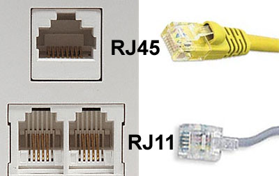
The biggest leap of faith to take for this system is the fact that a Cat5e cable can be terminated at the wall plate in such a way that it can be used as an Ethernet network connection OR a telephone jack. Traditionally, these jacks are considered separate and are separately installed. The picture below shows a typical wall plate with a data (or network) jack on the top; this is called an RJ45 jack (professionals in this area will point out that RJ45 not exactly the precisely correct naming protocol but this is how most people refer to it and it will work for our purposes here). And two phone jacks on the bottom; these are called RJ11 jacks. They are the familiar jacks you plug your telephones into.

Even though these appear to be two completely different shapes, the fact is the RJ45 jack is designed in such as way that it can be used with either an RJ45 OR an RJ11 plug. Really, it will work. As soon as I can figure out how to get a good close-up photograph of this I will show a picture. If you look closely at the shape of the RJ45 jack and then compare it to the shapes of the two different plugs, you will see how this can work. The RJ11 plug will naturally fit right into the middle part of the RJ45 jack. It will only go in there one way which is the right way, unless you are an absolute gorilla and just smash it in there the wrong way. Note that this wall plate more correctly labels the jacks as "Cat5e", not "RJ45". This makes sense now because as you can see that jack is connected to Cat5e cabling, which could be used for either networking with an RJ45 plug OR for telephone with an RJ11 plug.
Why do it this way at all? Why not just install both types of connectors at the wall plates? To me, using the RJ45 jacks only is at the same time simpler and more flexible. It is simpler because you have fewer types of jacks to purchase and install. It is more flexible because you can decide at any point in the future whether a wall plate port is going to be used for a phone or for a computer network connection. You don't have to decide in advance where your phone jacks should be - just decide everywhere you want a wall plate and then later put the phones wherever you want them. In order to make this work, the wiring needs to be configured properly at the other end. This is the whole point of the SW system, so you will have to read on to see how this is done. Installing the jacks in this way only has one drawback - it is possible that anyone who is unfamiliar with the details of the wiring system and who happens to need to plug in a phone will become confused about where they can and cannot plug in a phone. It is true that plugging a phone into a jack that has been activated for networking is not a desirable situation, although it is doubtful that any damage will occur. But the problem can be solved fairly easily by clearly labeling any wall plate that has been set up for phone as such. Then tell everyone to only plug a phone into a jack that has been labeled "phone". Exactly how this system can work will become clear once the entire system is explained.
So the final decision for the “standard” wall jack is to run a total of 4 wires, 2 Cat5e and 2 RG-6. This is a typical system that many installers will use. It is fairly standard practice nowadays to make the dual run of RG-6 to allow for good video distribution. Dual Cat5e allows for good flexibility for telephone, data, or possibly other uses. The general locations of the different wall jacks in each room are shown on the floor plan below. This floor plan includes a key to identify the number of ports at each wall plate and a color code to show Cat5e and RG6 ports. Some of the wall plates are different than the standard as determined by special requirements. The living room wall plate has 4 Cat5e instead of 2 to allow for extra connections that might be needed for an AV entertainment center. The bedroom #2 gets extra Cat5e and RG6 connections since it is used as an office and these will be needed to handle the tech gear. The kitchen and closet #1 just get a simplified wall plate with one of each to accommodate possible expansion for television in those locations.

If you wanted to, you could also draw the wiring connections to the wall plates in the floor plan. However, this is going to become a bit cluttered and difficult to read as you can see below. It would be even more cluttered if we tried to show each individual wire, such as 2 Cat5e and 2 RG6 going in a bundle to a wall plate. This type of drawing isn't really necessary since the drawing above is a clear description of the working end points, and it is understood that there will be wire going to each wall plate. However, it is valuable to have a comprehensive wiring diagram that shows every wire in the system and where it begins and end. That will be accomplished later with a block diagram rather than on a floor plan.

At this point, all of the wall plates are defined. There are a total of 8 wall plates in this plan. We know exactly how many individual wires need to be run to each wall plate, as defined by the number of ports. If you count them, you will see that there are a total of 38 wires that go from the wall plates to the wiring closet. Add in the 3 wires that are coming from the demarcation points and you have 41 wires total. The next step in the planning is to figure out what is happening with all of these wires where they all come together in the wiring closet.
Privacy Policy / Terms and Conditions | ©2000 -
2009 Schools Consulting