x•s•v•toys (ex-es-iv-toyz or excessive toys): Exceeding a normal, usual, reasonable, or proper limit for the purchase of consumer electronics. |
|
x•s•v•toys (ex-es-iv-toyz or excessive toys): Exceeding a normal, usual, reasonable, or proper limit for the purchase of consumer electronics. |
|
***UPDATE*** This retrofit structured wiring installation has been working with no problems since it was designed and installed in 2006, and most of the concepts are still valid today. However due to advances in technology some of the plans should be changed to accommodate the latest technological developments. Please review THIS UPDATE (CLICK HERE) before proceeding with any new plans for a home structured wiring project.
A good starting point is a floorplan. You use the floorplan to visualize what sort of system you want to develop, and then build the system up from there. Here is a typical floorplan for a single story house, which will be used as the example for this web site:

With the starting point of the floorplan, you can begin a systematic approach to your structured wiring planning that will be of greater and greater benefit as the project progresses. It will also be valuable further down the line after everything is complete to help with maintenance and future upgrades. Basically, you can just sort of “wing it as you go” and maybe get away with it, but things will be much better in the long run if you establish logical naming procedures. Plus, this is a fun exercise if you are sort of the "obsessive-compulsive" type who likes to sort, organize, categorize, and label things. You don’t have to use the system that is described here, you can come up with whatever system works good for you.
In this case, each room is labeled with a 3-character code. Note that all of the closets are also labeled. Even though you might not be thinking of sending any hi-tech wiring to your closets, it is still a good idea to label every separate space. You never know what the future will bring. And we will indeed be using at least one closet for this project.
This organizational scheme is valuable even if you plan to contract much or all of the work. It provides a way to clearly identify your intentions to help prevent mistakes. An instruction “place the wiring in BR3” (one possibility) is much less likely to be goofed than “place the wiring in the 2nd bedroom down the hall”(two possibilities).
One of the basic concepts of the structured wiring system is the “home run” for wiring. This means that all wiring originates to and from a single place. This home run location serves as the central control point where you can decide and determine what signals go to what locations. Note that some larger installations may have more than one home run location, but for our purposes, we will just have one. So an important decision to make early is where your home run will be. The home run location is also often called the wiring closet. Often it is located in a closet, although it doesn’t necessarily have to be.
The wiring closet does have to meet a few basic requirements. It must have enough room to mount the SW enclosure and any other items you might want to put there such as a cable modem or a router. It really doesn't take very much space to fit everything unless you are doing a huge project, and a typical small closet with sliding doors should work fine. The garage or basement are also popular places for the wiring closet. And importantly, you must have power available via an easily accessible AC outlet. If you don't have power there, you should plan to have an extra outlet installed there as part of your project. This sort of work is best done by a qualified electrician.
For this installation, closet # 4 (CL4) is selected. Reasons: Fairly decent attic access and proximity to main office and computer systems.
Next, we will identify the location of the various infeeds that are coming in. These include items such as:
You may have any combination of these inputs or infeeds. Each one will have its own entry point into the house. This is called a Demarcation Point. The demarcation point marks the position where the service provider’s responsibility ends and your responsibility (that is your own wiring) begins. The Demarcation Point might also be called the Point of Entry. Often, there is some sort of junction box that is mounted outside by the provider. This is called a Network Interface Device (NID). Sometimes the terms demarcation point and NID are used interchangeably.
In this example, we have the following infeeds.
Here they are marked on the floorplan (DP = Demarcation Point):

In this fairly typical residential arrangement, the cable is brought in to the roofline from a pole. Shown in the photo above is a splitter under the eave which splits the cable into three wires for delivery into the house. The phone DP is a typical telephone company (telco) installed box, with one wire coming in form the pole and another wire going back up and into the attic for delivery into the house.
Now with all of the external services identified, you have to confront the first major decision as a retro SW planner, which is whether you will use any of the existing wiring for your structured wiring plan. This may be a good possibility for you depending on the age of the house and the age and condition of any wiring that has already been installed. To help you make that decision, you will need to figure out what wires are already there and where they all go. Unless you have the benefit of planning documents from previous installations, you will have to figure this out the hard way by following around wires and trying to figure out what goes where. Your ability to do this will be greatly influenced by your specific arrangement. In this case, all of the wiring goes into the attic and is routed there and down the walls to the different room locations.
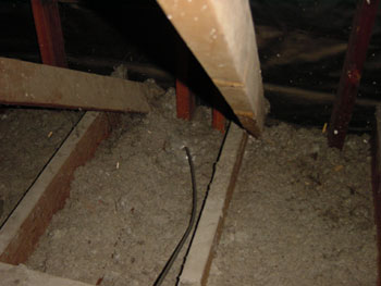
Typical Attic Wiring
A little bit if detective work shows that this house has a typical wiring pattern for residential homes in the US that are more than 10 or so years old: The phone wiring is not set up in the "home run" configuration which makes it pretty much impossible to reconfigure, and the cable is routed through the house via a series of splitters which is far from ideal as far as flexibility and also will tend to cause signal degradation. The floorplan below shows how this sort of arrangement looks.

Based on the way this wiring scheme is built, the decision was made to entirely scrap the existing wiring and to install all new wiring from the DPs into the house. So, the next step is to plan how that will be done.
Privacy Policy / Terms and Conditions | ©2000 -
2009 Schools Consulting